
Shiningintl Navigation Deception Spoofer C-UAV Anti-drone Solution Introduction
The Shiningintl Navigation Satellite Deception Counter Unmanned Aerial Vehicle(C-UAV) spoofer is designed for anti-drone and C-UAV scenarios in industries such as oil and petrochemicals, power, public security, and military applications. The board features a compact design, ease of use, and reliable performance, enabling rapid integration. Based on navigation satellite signal simulation technology, the board generates simulated satellite signals identical to real navigation satellite signals. Drones receiving these simulated signals will use them for positioning, allowing multiple deception modes such as course deviation, expulsion, forced landing, and rapid crash.
1.Technical Principles
Navigation-Based Counter-Drone Technology is a technical means to counteract drones by interfering with or spoofing their navigation systems. Its core principle involves simulating or disrupting signals from global satellite navigation systems (e.g., GPS, BeiDou, Galileo, GLONASS), causing drones to receive erroneous position, velocity, or timing information. This prevents drones from executing tasks normally or forces them into specific actions (e.g., returning, hovering, landing). Below is a detailed breakdown of the technology:
1)Signal Simulation (Signal Spoofing)
Generates false navigation signals via high-precision satellite signal simulators, overriding genuine satellite signals.
After receiving false signals, the drone’s positioning system misjudges its location, such as being “lured” to predefined false coordinates (e.g., diverting from no-fly zones or forced landing points).
Supports multi-frequency points (e.g., BDS-B1, GPS-L1) and multiple trajectory modes (linear, circular) to enhance spoofing flexibility.
2)Signal Suppression (Jamming)
Emits high-power jamming signals to suppress the reception of genuine satellite signals, depriving drones of positioning capabilities.
Some devices dynamically adjust jamming range and intensity to balance countermeasure effectiveness and electromagnetic environmental impact.
3)Collaborative Operation
Integrates sensors such as radar and electro-optical detection to locate drones in real time and synchronize false signal injection, improving countermeasure precision.
Core Functions
Multi-Mode Countermeasures: Supports spoofing (diverting flight paths), expulsion (forcing drones away from protected areas), forced landing, and rapid crash (for emergency scenarios).
Multi-System Compatibility: Covers GPS, BeiDou, GLONASS, and Galileo navigation systems, adapting to various drone navigation dependencies.
Dynamic Parameter Adjustment: Allows configuration of signal delay, motion speed, acceleration, and other parameters to simulate realistic flight states and reduce detection risks.
External Expansion: Supports direction-finding modules, preset trajectory imports, and network/serial control interfaces for seamless integration into existing security systems.
The technical theory of Shiningintl Navigation Satellite Deception C-UAV system is based on Signal Simulation (Spoofing), this system will generate the fraud GPS navigation signal and when the drone receives the fraud signal, it will do the operation as wanted.
2.Shiningintl Navigation Deception Spoofer C-UAV System Solution
The Shiningntl navigation deception spoofer device will receive the local GPS signals and then analyse their signals,it replaces the signal information according to the selected C-UAV methods. The spoofing system mainly consists of the following parts:
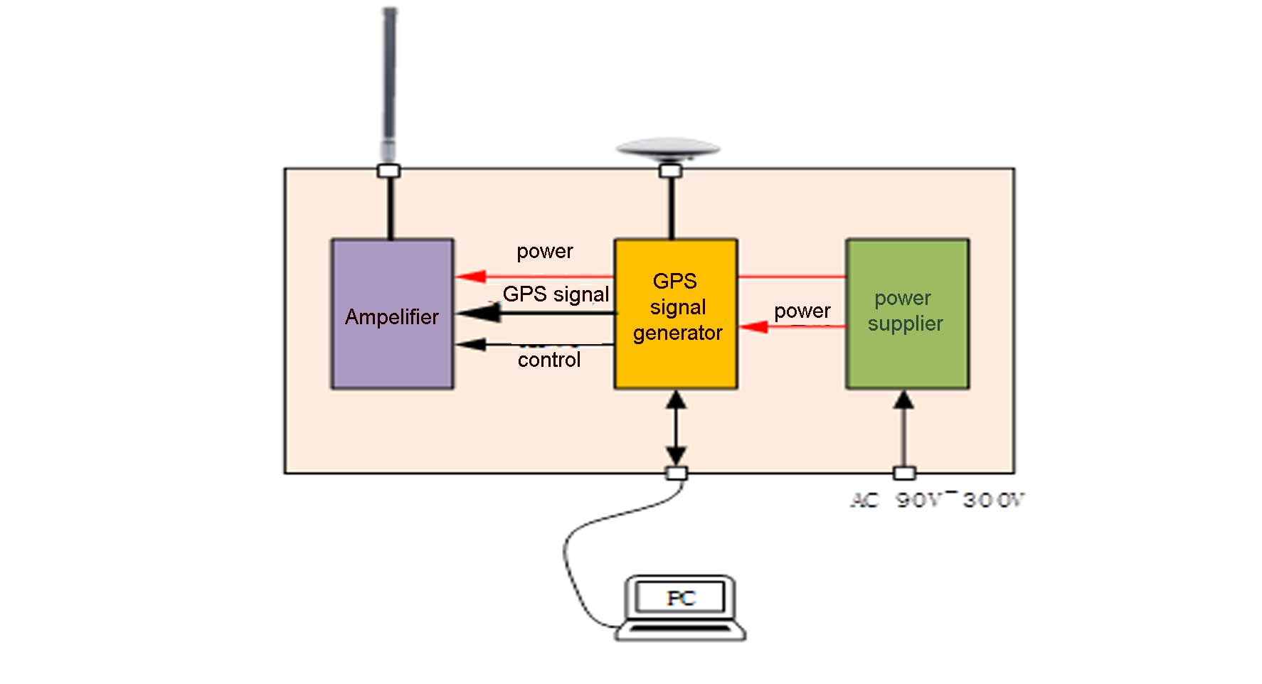
- Structural shell
- Power amplifier module
- Power supply
- Transmitting antenna
- Receiving antenna(to receive the local GPS signals)
- Navigation signal simulation source
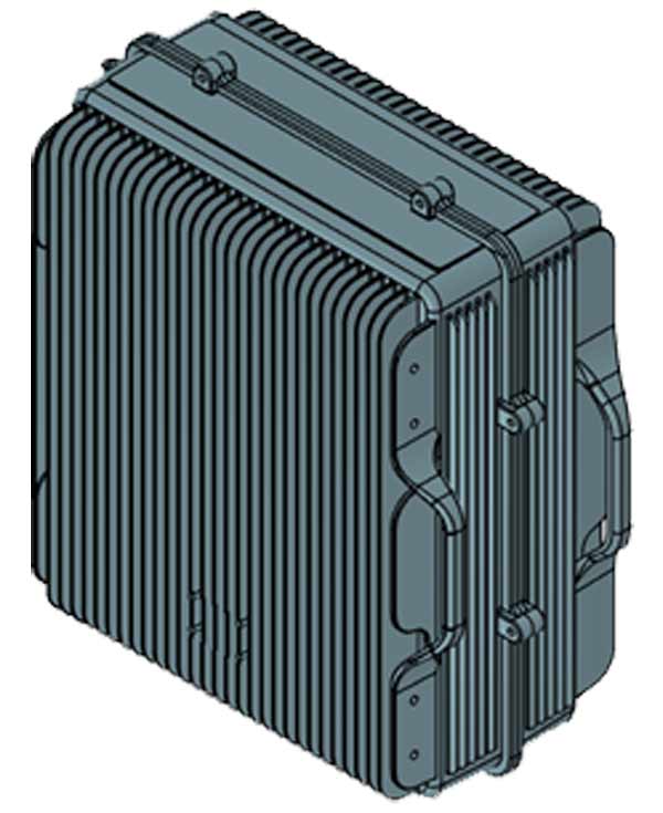
Structural shell
The structure uses cast aluminum structure, The structure of a 100W power amplifier is shown below, and other powers can be re evaluated according to requirements:
Power amplifier module
How to calculate the rated power of the amplifier?
The output power of the power amplifier module needs to be selected based on the coverage range. According to experience, a 20W power amplifier can cover 15Km.
According to the radio space attenuation formula and empirical values for 20W coverage of 15Km, the relationship between distance and power can be calculated using the following formula:
P(dBm ) = 43dBm +20*log(d/15)
Among them, the unit of P is dBm, and the unit of d is Km.
If covering a distance of 30Km, substituting the above equation yields: P=49dBm ≈ 80(W)
Power module
Power consumption for project design: one power supply for 20W, two power supplies for 50W, and two power supplies for 100W
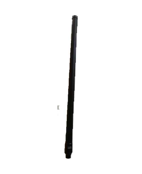
Transmitting antenna
The transmitting antenna is mainly used for transmitting navigation signals in equipment. Need to cover the navigation signal frequency band, as shown in the following figure:
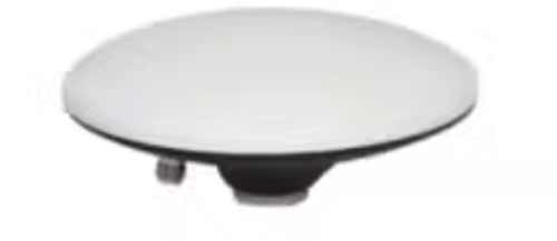
Receiving antenna
The receiving antenna is mainly used for the navigation signal source in the device to receive GNSS signals. Need to meet the reception requirements of BDS, GPS, GLONASS, and GALILEO navigation signals. The appearance diagram is shown in the following figure:
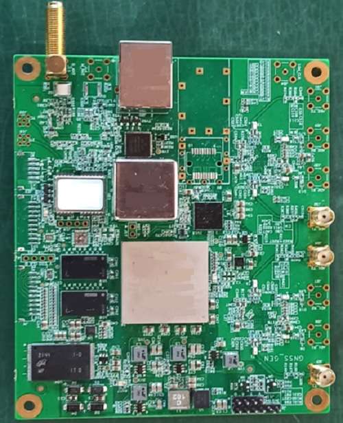
Navigation signal simulation source
This unit will generate the GPS signal according to the what kind of operation you want the drone to do, the signal will create the deception signal, the signal will go through the amplifier unit and the transmitting anttena, then extend to the sky.
3.Shiningintl Navigation Deception C-UAV System technical specification
Product Features
- Supports signal reception and simulated transmission for common frequency points of the four major global navigation satellite systems.
- Deceives drones reliant on satellite navigation systems to achieve objectives such as forced landing, course deviation, takeoff prevention, and signal interference.
- Supports external direction-finding modules to identify target orientation and control horizontal movement (forward, backward, left, right) via course deviation.
- Allows external command control for arbitrary navigation signal combinations.
- Enables external command configuration of arbitrary coordinates (longitude, latitude, altitude) or preset fixed coordinates.
- Adjusts simulated parameters (signal delay, motion speed, acceleration) via external commands.
- Supports preset trajectories (linear, circular) and external trajectory injection for dynamic signal output.
- Operates in real-time ephemeris mode or permanent ephemeris mode.
- Auto-transmits preset coordinates upon power-up.
- Provides satellite navigation signal suppression and jamming output.
- Offers secondary development interfaces: serial (RS422) and Ethernet (RJ45).
Key Technical Specifications
Technical Parameters
- Supported Systems & Frequencies:
| No. | Satellite System | Frequency Band | Channels |
| 1 | BDS | B1I | 16 |
| 2 | GPS | L1 C/A | 16 |
| 3 | GLONASS | L1 | 16 |
| 4 | Galileo | E1 | 16 |
- Signal Reception Frequencies: BDS-B1, GPS-L1, GLONASS-L1, Galileo-E1.
- Max Transmission Power: ≥-10dBm.
- Power Adjustment Range: 80dB (1dB resolution).
- Startup Time: 40s.
- Signal Synchronization Time: <180s.
Physical Dimensions & Interfaces
- Dimensions (excluding connectors): 120mm (L) × 100mm (W).
- Weight: <150g.
- Power:
- Input Voltage: DC 10–28V.
- Power Consumption: ≤9W.
- Interfaces:
- Signal Input: SMA port (supports DC +5V feed).
- Signal Output: SMA port.
- Power Input: XH2.5-2P male connector.
- Serial Communication: HC-ZH-4PWT (RS422).
- Ethernet: RJ45.
Operating Environment
- Operating Temperature: -40℃ to +60℃.
- Storage Temperature: -40℃ to +80℃.
Contact Shiningintl for more information: https://www.shiningintl.com