
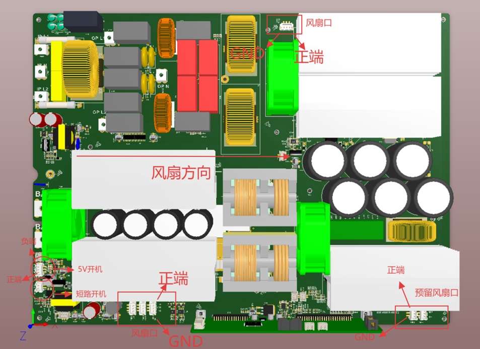
7200W bidirectional splited phase(110VAC and 220V AC) power inverter system
Product Description
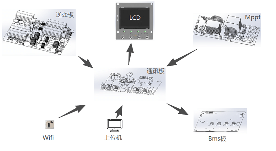
The Shiningintl PK7200 whole power system consists of a splited phase 7200W inverter, a communication board, an MPPT module and a display screen, wherein the communication board is used as an intermediate module and internally communicates with the inverter and the MPPT module to acquire information such as machine state power and the like, simultaneously communicates with the BMS to acquire battery-related information, and can also communicate with an external upper computer or a wifi module and the like to acquire or transmit information, And the machine information can be visually displayed to the user through the display screen.
| Model | PK7200-48V | |
| Inverter module | Rated power | 7200W |
| Peak power | 15000W | |
| Number of output phases | 120/240Vac | |
| Number of output lines | Two-phase three-wire (L1, N, L2) + ground | |
| Working mode | Off-grid, grid-connected, grid-connected and off-grid (off-grid, grid-tied, Hybrid) | |
| Conversion time | <10ms | |
| Rated output voltage | 120/240Vac | |
| Output voltage accuracy | ±2% | |
| Bypass rated current | 40A | |
| Output frequency | 50/60Hz±0.1Hz | |
| Output waveform distortion | <3% @R load <7% @Non-Linear load | |
| Overload | 102% ~ 120% 20s 120% ~ 150% 2s >150% 400ms | |
| Discharge efficiency | 95% | |
| No-load loss | 9W @ standby mode; 50W @ inverter no-load mode | |
| Number of AC input phases | 120/240Vac split phase | |
| Number of AC input lines | Two-phase three-wire (L1, N, L2) + ground | |
| AC input range | L-N: 80~145Vac | |
| AC Input Frequency Range | 50Hz: 46~54Hz (default); 60Hz: 56~64Hz (default); 30~80Hz (allow) | |
| Input power factor | >0.98 | |
| Charging efficiency | >96% | |
| Maximum charge current | 100A | |
| Charging voltage range | 40V~60V | |
| Precharge current | 1~3A | |
| Charging control method | Pre-charge, constant current, constant voltage, equalizing charge, floating charge, shutdown | |
| Applicable battery type | Lead Acid (Flooded)/Gel (GEL)/AGM/Lithium Battery/Custom | |
| MPPT module | Maximum input power | 9kW |
| Number of MPPT channels | 2 | |
| Maximum open circuit voltage | 500V | |
| Input voltage range | 80-450Vdc | |
| Rated input voltage | 100~400Vdc | |
| Turn-on voltage | 100Vdc | |
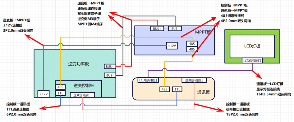
1 Schematic Diagram of Internal Wiring
The system is composed of inverter board, communication board, MPPT board and display screen. The wiring diagram is as follows:
Test Description
1. Open Output
After the battery and the BMS communication line are connected, use the physical short circuit switch to continuously short circuit or continuously provide 5V power supply, the display screen lights up to indicate that the machine has been awakened, and then wait for the machine to turn on the AC output.
2 Output with Load
It can be separately connected to L1 + N or L2 + N with 120V low-voltage load, with a maximum load of 3600 W for each circuit, or connected to L1 + L2 with 240V high-voltage load, with a maximum load of 7200W. Overload protection will be triggered if the maximum load is exceeded.
3 Mains Charging
IP.L1, IP.L2 and IP. N need to be connected at the same time. The phase difference between IP.L1 and IP.L2 is 180 °. Note that it is not allowed to connect IP.L1 and IP.L2 only. The N line also needs to be connected. If the use scenario is that the input is connected to IP.L1 + LP. N or IP.L2 + LP. N separately, the inverter board program needs to be updated. After the mains supply is connected, wait for the machine to automatically enter the charging mode. The charging current of the battery can be set through item 02 of the LCD panel setting interface.
4 PV Charging
One PV can be connected separately or two PVs can be connected at the same time, but one PV output can not be connected to two inputs at the same time. The open circuit voltage of PV is 450 V. After the PV is connected, the machine will charge itself.
4.5 Charging Priority Test
The charging priority can be set through the screen setting interface.
① PV charging priority: PV gives priority to battery charging, and only when the PV system fails, it will be charged by the grid.
② Priority of mains supply charging: The mains supply shall be used to charge the battery. Only when the mains supply is interrupted, the photovoltaic charging can be started.
③ Hybrid charging: photovoltaic and mains hybrid charging mode. PV charging is a priority mode, when the PV power supply is insufficient, the electric quantity is supplemented by the mains supply; When the photovoltaic power supply is sufficient, the mains supply stops charging.
④ Only PV charging: only the photovoltaic panel is used for charging, and the commercial power is not used for charging;
4.6 Discharge Priority Test
Discharge priority can be set through the screen setting interface.
① PV power supply priority: give priority to PV discharge, insufficient PV is supplemented by the battery, when there is no PV or the battery reaches the set protection SOC or voltage, it is switched to mains discharge.
Power priority: PV → Battery → Grid
② Priority of mains supply: give priority to mains discharge, and switch to inverter discharge only when the mains supply is interrupted.
Power Priority: Grid → PV → Battery
③ Priority of battery power supply: give priority to inverter discharge, and use mains discharge only when DC reaches the set protection SOC or voltage.
Power priority: PV → Battery → Grid
④ Hybrid power supply: PV discharge is preferred. When PV is insufficient, the mains supply and inverter supply the load together. When the mains supply is interrupted or the mains supply is insufficient, it will be supplemented by the battery.
Power priority: PV → grid → battery


