
Shiningintl PK-6000 Modbus Bidirectional Inverter — Work-Mode State Machine
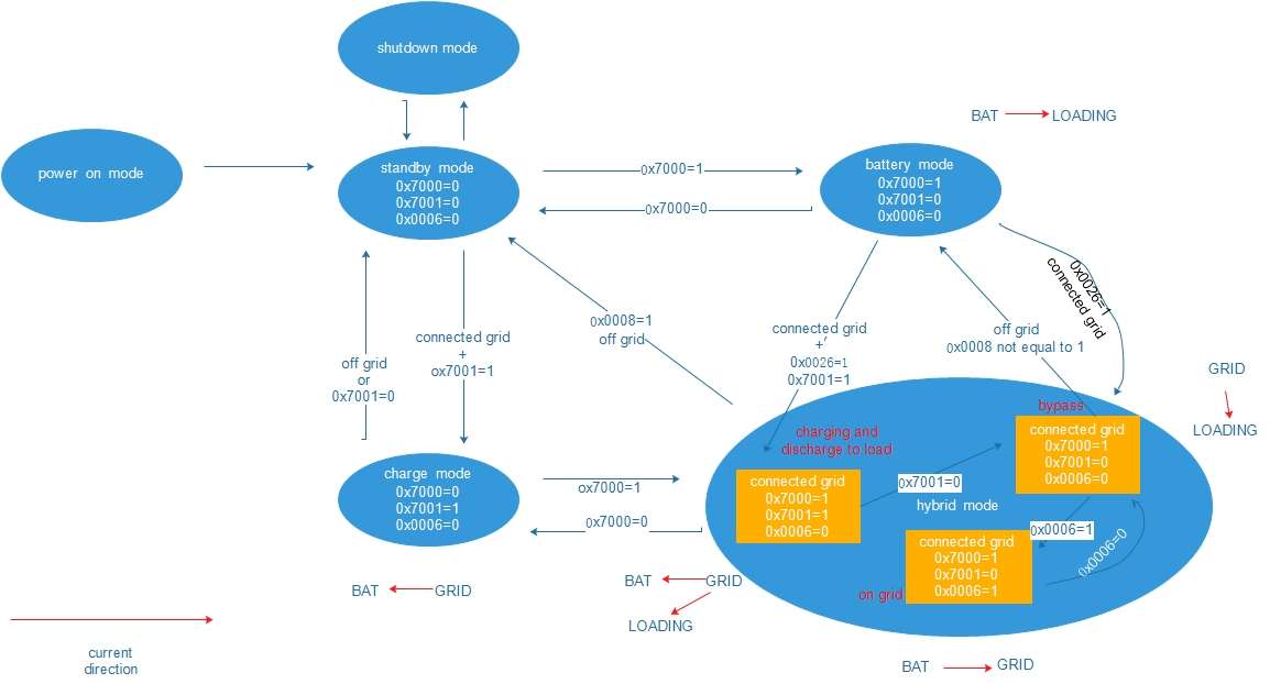
The PK-6000 inverter is an powerful on grid tier bidirectional inverter can apply in wide arrange, it adopts the MODBUS protocols to provide the strong communication, this document will show how to operate the inverter with a clear state machines. The users can operate the inverter as their requirements according this document. The PK-6000 operates through several main states: Power-On Mode, Standby Mode, Shutdown Mode, Battery Mode, Charge Mode, and Hybrid Mode. The inverter changes between these states according to the grid connection status and the control registers.
In order to keep the inverter safe, feeding power back to the grid only available within the hybrid mode
1.Register
| register | Function description | Notes |
| 0x7000 | AC Output enable flag | 0:turn off AC output 1:turn on AC output |
| 0x7001 | Charging enable flag | 0:turn off battery charging 1:turn on battery charging |
| 0x0006 | Output to grid endbale flag | 0:disable to output to grid 1:enable to output to grid |
| 0x0008 | Supplier Priority to loading | 0:PV first,then battery 1:grid first 2:PVfirst, battery second ,then grid 3:PV first,and then grid |
| 0x0025 | automatically switch to bypass flag | 0: disable automatically switch to bypass mode if the grid available 1:enable automatically to switch to bypass mode if grid available |
2. States and Their Register Signature
| State | Register signature as drawn in the box | Notes |
| power on mode | Turn on the power | initial state, no registers shown |
| shutdown mode | Shut down the power | no registers shown |
| standby mode | 0x7000=0, 0x7001=0, 0x0006=0 | idle / no work mode active |
| battery mode | 0x7000=1, 0x7001=0, 0x0006=0 | inverter (battery → load) |
| charge mode | 0x7000=0, 0x7001=1, 0x0006=0 | charger (grid → battery) |
| hybrid mode | container (super-state) with the label “hybrid mode” | holds three sub-states, all prefixed “connected grid” |
Sub-states inside hybrid mode (orange boxes, red annotations)
| Sub-state annotation | Register signature | Meaning |
| charging and output to load | connected grid, 0x7000=1, 0x7001=1, 0x0006=0 | grid available to charging and grid feeds the load |
| bypass | connected grid, 0x7000=1, 0x7001=0, 0x0006=0 | grid feeds the load, not charging |
| on grid | connected grid, 0x7000=1, 0x7001=0, 0x0006=1 | grid-tied, power is fed to the grid from inverter |
3. Start-up and Shutdown
- 1. power on mode → standby mode — when the inverter is power on, it will automatically enter the standby mode
- 2. standby mode → shutdown mode — when the switch is turn of f or received turn off command, the inverter will shutdown.
4. Transitions Between Working Modes
| From | To | Condition on the arrow |
| standby mode | battery mode | 0x7000=1 |
| battery mode | standby mode | 0x7000=0 |
| standby mode | charge mode | connected grid + 0x7001=1 |
| charge mode | standby mode | off grid or 0x7001=0 |
| charge mode | hybrid mode | 0x7000=1 |
| hybrid mode | charge mode | 0x7000=0 |
| battery mode | hybrid mode (enters charging and discharge to load) | connected grid + 0x0025=1 + 0x7001=1 |
| battery mode | hybrid mode (enters bypass) | connected grid + 0x0025=1 (curved arrow) |
| hybrid mode | battery mode | off grid + 0x0008 not equal to 1 |
| hybrid mode | standby mode | 0x0008=1 + off grid |
5. Transitions Inside hybrid mode
| From | To | Condition |
| connected grid and charging (0x7001=1, 0x0006=0) | connected grid (bypass) | 0x7001=0 |
| connected grid (bypass) | connected grid (0x0006=1, on grid) | 0x0006=1 |
| connected grid (0x0006=1, on grid) | connected grid (bypass) | 0x0006=0 |
6. Power- current direction
| Where | Annotation |
| battery mode (top right) | BAT → LOADING |
| hybrid mode: bypass (right side) | GRID → LOADING |
| hybrid mode: charging and discharge to load (bottom left) | BAT ← GRID and GRID → LOADING |
| hybrid mode: on grid (bottom) | BAT → GRID |
| charge mode (bottom left) | BAT ← GRID |
7. Plain-Language Walkthrough
The unit boots from power on mode into standby mode (0x7000=0, 0x7001=0, 0x0006=0) and can be put into shutdown mode
From standby the unit branches into one of two single-purpose modes:
- setting 0x7000=1 starts battery mode — the inverter feeds the load from the battery (BAT → LOADING); clearing 0x7000 to 0 returns to standby;
- with the grid connected and 0x7001=1 it enters charge mode — the grid charges the battery (BAT ← GRID); it returns to standby when the grid is lost (off grid) or when 0x7001 is cleared to 0.
hybrid mode is the only mode with an internal state machine and is entered from charge mode by setting 0x7000=1, and from battery mode when the grid is connected and 0x0025=1 (with 0x7001=1 it drops directly into the charging and discharge to load sub-state, otherwise into bypass). Inside hybrid mode all three sub-states share connected grid and 0x7000=1:
- charging and output to load (0x7001=1, 0x0006=0) — the load will adopt the grid power, battery also charges from the grid;
- clearing 0x7001 → bypass (0x0006=0) — the grid alone supplies the load;
- setting 0x0006=1 → on grid (0x0006=1), where the battery can push power back to the grid (BAT → GRID); clearing 0x0006 returns to bypass.
hybrid mode is left by clearing 0x7000 (→ charge mode), or when the grid is lost: off grid with 0x0008 not equal to 1 returns to battery mode, while 0x0008=1 with off grid returns to standby mode.
8. Notes on the Drawing (not on the protocol)
- 0x0008 appears on both arrows leaving hybrid mode (the two are distinguished by “not equal to 1” vs. “=1”), and 0x0025=1 appears on both arrows from battery mode into hybrid mode; the register meaning is not defined on the diagram, so the two pairs can only be told apart by direction and target sub-state.
- Every register value shown in a state box is the value that state is expected to report (0x7000 = work-mode active, 0x7001 = charger active, 0x0006 = grid-tie/bypass flag, 0x0008 / 0x0026 = grid/hybrid conditions). That reading is inferred from the pattern of the boxes — the diagram itself only lists the numbers.