
Table of Contents
1. Executive Summary
2. System Architecture & Block Diagram
3. Core Components
3.1 Bidirectional Inverter Board (2400W / 3600W)
3.2 BMS Board (H120-B, 16S LiFePO4, 60A)
3.3 Control Panel
3.4 48V Battery Pack (Customer-Supplied)
4. Technical Specifications
5. Communication Protocol (RS485 / Modbus RTU)
6. DIY Assembly Guide
7. Ordering Information
8. Contact & Support
1. Executive Summary
SHININGINTL presents a complete DIY Portable Power Station solution that empowers customers to build their own high-performance portable power station. By purchasing SHININGINTL’s core electronic components and sourcing a standard 48V battery pack and enclosure separately, customers can create a customized portable power solution tailored to their specific needs.
The SHININGINTL DIY Kit includes three essential core components:
Bidirectional Inverter Board (2400W / 3600W) – Provides AC output, AC charging, and MPPT solar charging in a single board
BMS Board (H120-B) – 16S LiFePO4 Battery Management System with comprehensive protection and RS485 communication
Control Panel – User interface with LCD display, USB fast charging ports, DC outputs, and system control buttons
Customers only need to add:
48V 16S LiFePO4 Battery Pack (readily available in the market)
Custom Enclosure / Housing (of the customer’s choice)
Wiring, connectors, and accessories
This modular approach offers maximum flexibility, cost efficiency, and customization options while ensuring professional-grade performance and safety through SHININGINTL’s rigorously tested core electronics.
2. System Architecture & Block Diagram
The following block diagram illustrates the system architecture of the DIY Portable Power Station. The system is built around four main functional blocks interconnected to deliver a complete power solution.
2.1 System Block Diagram
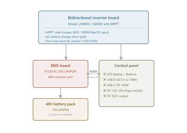
Figure 1: System Block Diagram of SHININGINTL DIY Portable Power Station
3. Core Components
3.1 Bidirectional Inverter Board (2400W / 3600W)
The SHININGINTL Bidirectional Inverter Board is the heart of the portable power station. It integrates three key functions into a single, compact PCB:
Pure Sine Wave AC Inverter (2400W or 3600W output)
AC Battery Charger (charges battery from grid power)
MPPT Solar Charge Controller (maximizes solar energy harvesting)
Key Features:
True bidirectional power conversion – single board handles both AC to DC (charging) and DC to AC (inverting)
Pure sine wave output suitable for sensitive electronics
Built-in MPPT solar charger with 60V maximum PV open-circuit voltage
High efficiency power conversion
Overload, over-temperature, and short-circuit protection
Designed for 48V battery systems (16S LiFePO4)
Inverter Board – Top View:

Figure 2: Bidirectional Inverter Board – Top View
3.2 BMS Board (H120-B, 16S LiFePO4, 60A)
The H120-B Battery Management System (BMS) board provides comprehensive protection and monitoring for 16-series LiFePO4 (Lithium Iron Phosphate) battery packs. It employs a common-port design where charging and discharging share the same power path.
Key Features:
Designed for 16S LiFePO4 battery configuration (48V nominal)
60A continuous charge / discharge current rating (common port)
Software-programmable BMS with intelligent monitoring
Individual cell voltage monitoring (16 channels)
Cell balancing function
Multi-point temperature sensing (cell temperature + PCB temperature)
RS485 communication interface (Modbus RTU protocol)
State of Charge (SOC) and State of Health (SOH) calculation
Cycle count tracking
Protection Features:
Cell over-voltage / under-voltage protection
Pack over-voltage / under-voltage protection
Charge over-temperature / low-temperature protection
Discharge over-temperature / low-temperature protection
Charge over-current protection
Discharge over-current protection
Short-circuit protection
Reverse polarity protection
BMS Board:
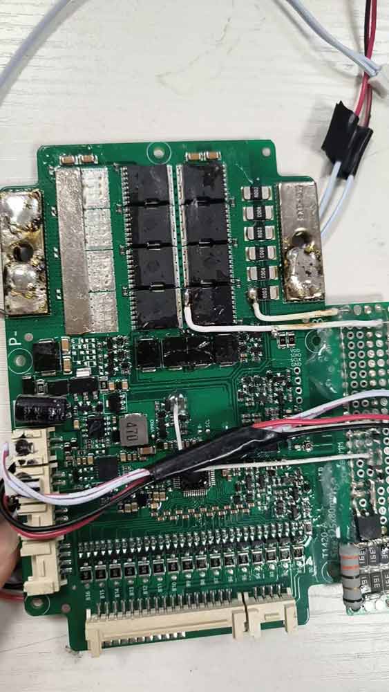
Figure 4: H120-B BMS Board (16S LiFePO4, 60A Common Port)
3.3 Control Panel
The Control Panel serves as the user interface for the portable power station. It features an LCD display for system status monitoring and provides multiple output ports for various devices. The panel communicates with the inverter board and BMS via RS485 to display real-time system information.
Key Features:
LCD display showing comprehensive system status
2x USB-A QC3.0 fast charging ports (18W max each)
1x USB-C PD 3.0 port (100W max, supports PPS, PD3.0, PD2.0, QC4+)
1x Cigarette lighter socket (DC 12V – 10A)
2x 5521 DC output jacks (12V – 10A, shared with cigarette lighter circuit)
1x LED light board output
4 control buttons (Light, USB/BMS, DC Output, AC Output)
Solar charging interface (connects to inverter MPPT input)
48V battery input (16S, connects to BMS)
RS485 communication with BMS and inverter
Display Information:
| Display Item | Data Source | Description |
| Input Power | Inverter & DC Board | Real-time charging power from solar or AC |
| Output Power | Inverter & DC Board | Real-time output power consumption |
| Battery Capacity | BMS | State of Charge (SOC) percentage indicator |
| AC Output Indicator | Inverter Board | AC output on/off status |
| USB-A Indicator | DC Board | USB Type-A output status |
| USB-C Indicator | DC Board | USB Type-C output status |
| DC 12V Indicator | DC Board | Cigarette lighter / 5521 output status |
| Fault Alarm | BMS & Inverter | Battery or inverter fault indication |
| High Temp Alarm | Inverter & BMS | High temperature warning |
| Low Temp Alarm | Inverter & BMS | Low temperature warning |
| Fan Indicator | Inverter Board | Cooling fan status |
| PV Input Indicator | Inverter Board | Solar panel input status |
| Charging Indicator | Inverter Board | Battery charging status |
| Fault Code | Inverter & BMS | Error code display in power area |
Table 1: Control Panel Display Items
Control Panel Board:
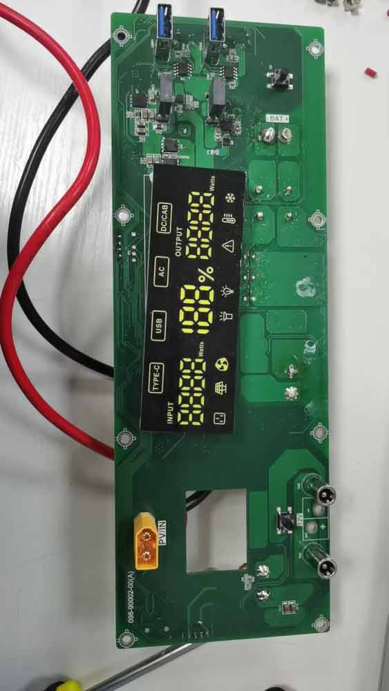
Figure 5: Control Panel / Main Control Board
3.4 48V Battery Pack (Customer-Supplied)
The 48V battery pack is the energy storage component of the system. Customers source this independently, providing flexibility in capacity, brand, and budget. SHININGINTL recommends the following specifications to ensure compatibility and optimal performance:
Recommended Battery Specifications:
Chemistry: LiFePO4 (Lithium Iron Phosphate)
Configuration: 16 cells in series (16S)
Nominal Voltage: 48V DC (51.2V nominal for 16S LiFePO4)
Voltage Range: 40V to 58.4V DC
Recommended Capacity: 50Ah to 100Ah (approximately 2.5kWh to 5kWh)
Must be compatible with external BMS (H120-B) for protection and monitoring
Cell balancing wires must be accessible for BMS connection
The battery pack connects to the H120-B BMS board which provides all protection and monitoring functions. The BMS then interfaces with the bidirectional inverter board for charging and discharging control.
4. Technical Specifications
4.1 System Overview
| Parameter | Specification |
| System Topology | Bidirectional Inverter + External BMS + Control Panel + 48V Battery |
| AC Output Power | 2400W or 3600W (model dependent) |
| AC Output Waveform | Pure Sine Wave |
| Battery Type | 16S LiFePO4 (48V nominal, customer-supplied) |
| Solar Input | MPPT, 60V max PV open-circuit voltage, 500W rated |
| Communication | RS485 / Modbus RTU |
| Cooling | Forced air cooling (temperature-controlled fan) |
| User Interface | LCD display + 4-button control panel |
Table 2: System Overview Specifications
4.2 Bidirectional Inverter Board – MPPT Solar Charging
| Parameter | Specification |
| Maximum PV Open-Circuit Voltage | 60V (Max 500W) |
| PV Working Voltage Range | 9.5 – 60V DC |
| MPPT Voltage Range | 9.5 – 60V DC |
| Battery Voltage Range | 40 – 60V DC |
| Maximum Charging Power | 800W |
| PV Charging Current Range | 0 – 20A |
| Reverse Polarity Protection | Yes |
Table 3: MPPT Solar Charging Specifications
4.3 Control Panel – USB-A QC3.0 Ports (2x)
| Parameter | Specification |
| Port Type | USB Type-A |
| Quantity | 2 ports |
| Supported Protocols | QC3.0, QC2.0, FCP, AFC, BC1.2, Apple 2.4A |
| 5V Output | 3.0A (15W) |
| 9V Output | 2.0A (18W) |
| 12V Output | 1.5A (18W max) |
| Output Ripple | less than 150mVp-p |
| Over-Current Protection | Yes, auto-recovery via button |
| Short-Circuit Protection | Yes, auto-recovery via button |
| Anti-Backfeed Protection | Yes |
Table 4: USB-A QC3.0 Port Specifications
4.4 Control Panel – USB-C PD Port
| Parameter | Specification |
| Port Type | USB Type-C |
| Quantity | 1 port |
| Supported Protocols | PD 3.0, PPS, PD 2.0, QC4+, AFC, FCP, SCP |
| Maximum Power | 100W (20V / 5A) |
| 5V Output | 3.0A |
| 9V Output | 3.0A |
| 12V Output | 3.0A |
| 15V Output | 3.0A |
| 20V Output | 5.0A (100W max) |
| Output Ripple | less than 150mVp-p (5-15V), less than 200mVp-p (20V) |
| Plug-and-Play | Yes (supports PD protocol devices) |
| Short-Circuit Protection | Auto-recovery |
Table 5: USB-C PD Port Specifications
4.5 Control Panel – DC 12V Output (Cigarette Lighter / 5521)
| Parameter | Specification |
| Output Type | Cigarette Lighter Socket + 2x 5521 DC Jacks |
| Output Voltage | 12V DC |
| Maximum Current | 10A (shared across all DC outputs) |
| Short-Circuit Protection | Auto-recovery |
Table 6: DC 12V Output Specifications
4.6 BMS Board (H120-B)
| Parameter | Specification |
| Model | H120-B |
| Battery Chemistry | LiFePO4 (Lithium Iron Phosphate) |
| Series Configuration | 16S (16 cells in series) |
| Nominal Voltage | 48V / 51.2V |
| Continuous Current | 60A (common port – charge and discharge) |
| Communication | RS485 (Modbus RTU) |
| Cell Monitoring | 16 individual cell voltage channels |
| Temperature Sensing | Cell temperature + PCB temperature (multiple NTC probes) |
| SOC / SOH Calculation | Yes |
| Cell Balancing | Yes (configurable) |
| Cycle Counter | Yes |
| Protection Features | Over/under voltage, over current, short circuit, over/low temp, reverse polarity |
| Baud Rate | 9600 bps, 8 data bits, 1 stop bit, no parity |
Table 7: H120-B BMS Specifications
5. Communication Protocol (RS485 / Modbus RTU)
The system uses RS485 physical layer with Modbus RTU protocol for communication between the BMS board and the control panel / inverter. This allows real-time monitoring of battery status, system parameters, and fault conditions.
5.1 Physical Layer Parameters
| Parameter | Value |
| Interface | RS485 |
| Baud Rate | 9600 bps |
| Data Bits | 8 |
| Stop Bits | 1 |
| Parity | None |
| Device ID | 1 (default) |
Table 8: RS485 Communication Parameters
5.2 Frame Format
Request Frame: [ID: 1Byte] [CMD: 1Byte] [SAD: 2Bytes] [DLEN: 2Bytes] [CRC: 2Bytes]
Response Frame: [ID: 1Byte] [CMD: 1Byte] [DLEN: 2Bytes] [DATA: nBytes] [CRC: 2Bytes]
The CRC is a 16-bit Modbus CRC calculated over all preceding bytes (ID through DLEN/DATA). MSB-first byte ordering for data fields; CRC is transmitted LSB-first.
5.3 Key Data Registers
| Address | Data Name | Unit | Type | Description |
| 0x01 | Total Voltage | 10mV | UINT16 | Battery pack total voltage |
| 0x02 | Current | 10mA | INT16 | Charge/discharge current |
| 0x03-0x04 | Remaining Capacity | 10mAh | UINT32 | Remaining battery capacity |
| 0x05-0x06 | Full Charge Capacity | 10mAh | UINT32 | Full charge capacity |
| 0x07 | State of Charge (SOC) | % | UINT16 | Battery SOC percentage |
| 0x08 | Cycle Count | – | UINT16 | Charge/discharge cycle count |
| 0x09 | Cell Count | – | UINT16 | Number of series cells |
| 0x0A | State of Health (SOH) | % | UINT16 | Battery health |
| 0x0B | Protection Flags | – | UINT16 | Active protection status (see Table 10) |
| 0x0C | MOSFET Status | – | UINT16 | Charge/discharge MOSFET state |
| 0x0D | Production Date | – | UINT16 | BMS manufacturing date code |
| 0x0E | Firmware Version | – | UINT16 | BMS firmware version |
| 0x0F | Balance Flags | – | UINT16 | Cell balancing enable status (16 bits) |
| 0x10 | BMS Allowed Charge Current | mA | INT16 | Current charge current limit |
Table 9: Key Modbus Registers for System Monitoring
5.4 Protection Flags Register (0x0B) Bit Definitions
| Bit | Protection | Description |
| Bit 0 | Cell Over-Voltage | Individual cell voltage exceeds upper limit |
| Bit 1 | Cell Under-Voltage | Individual cell voltage below lower limit |
| Bit 2 | Pack Over-Voltage | Total pack voltage exceeds upper limit |
| Bit 3 | Pack Under-Voltage | Total pack voltage below lower limit |
| Bit 4 | Charge Over-Temp | Charging temperature too high |
| Bit 5 | Charge Low-Temp | Charging temperature too low |
| Bit 6 | Discharge Over-Temp | Discharging temperature too high |
| Bit 7 | Discharge Low-Temp | Discharging temperature too low |
| Bit 8 | Charge Over-Current | Charging current exceeds limit |
| Bit 9 | Discharge Over-Current | Discharging current exceeds limit |
| Bit 10 | Short Circuit | Output short circuit detected |
| Bit 11 | IC Error | Front-end monitoring IC error |
| Bit 12 | Software Lock | MOSFETs locked by software |
Table 10: Protection Flags Bit Definitions
6. DIY Assembly Guide
This section provides a high-level guide for assembling the DIY Portable Power Station. Customers with basic electronics knowledge should be able to complete the assembly following these steps.
6.1 Prerequisites
Required SHININGINTL Components:
SHININGINTL Bidirectional Inverter Board (2400W or 3600W model)
SHININGINTL H120-B BMS Board
SHININGINTL Control Panel
Customer-Supplied Items:
48V 16S LiFePO4 Battery Pack
Custom enclosure (with adequate ventilation)
DC-rated wiring (appropriate gauge for 60A+ current)
AC input connector and circuit breaker
AC output sockets (compatible with local electrical standard)
Solar panel input connector (MC4 or equivalent)
Basic tools: screwdrivers, wire strippers, crimping tools, multimeter
6.2 Assembly Steps
Step 1: Prepare the Enclosure
Plan component layout with adequate airflow for cooling
Drill / cut openings for control panel, AC outlets, input connectors, and ventilation fans
Mount component standoffs and brackets
Step 2: Install the Battery Pack
Secure the 48V battery pack in the enclosure
Connect battery main power cables (positive and negative) to the BMS board
Connect cell balance wires (B1 through B16) from each cell to the BMS balance connector
Connect temperature sensors (NTC probes) to battery cells
Step 3: Install the BMS Board
Mount the H120-B BMS board securely
Connect RS485 communication cable from BMS to control panel
Connect BMS power output to the inverter board DC input
Double-check all connections with a multimeter before proceeding
Step 4: Install the Bidirectional Inverter Board
Mount the inverter board with adequate clearance for cooling
Connect DC input from BMS/battery to the inverter board
Wire AC output to the output sockets / circuit breaker
Wire AC charging input from grid input connector
Connect solar panel input to MPPT terminals
Connect cooling fan to the fan output connector
Step 5: Install the Control Panel
Mount the control panel to the enclosure front face
Connect RS485 communication cable from BMS
Connect all output port wiring (USB, DC, LED light)
Connect button / switch wiring
Step 6: Final Connections and Testing
Connect system ground / earth wiring
Install fuses / circuit breakers as appropriate
Perform continuity and isolation checks on all connections
Power on system and verify operation via LCD display
Test all output ports with appropriate loads
Test charging from AC grid and solar panel (if available)
6.3 Important Safety Notes
ALWAYS disconnect battery power before working on the system
Ensure proper ventilation – the inverter generates significant heat during operation
Use properly rated fuses / circuit breakers on all power paths
Follow local electrical codes and safety regulations
Do not exceed the rated power output of the inverter (2400W / 3600W)
Use only LiFePO4 chemistry batteries rated for 16S configuration
SHININGINTL is not responsible for damage caused by improper assembly or use of non-approved components
Keep the system dry and away from flammable materials during operation
7. Ordering Information
SHININGINTL provides the following core components for the DIY Portable Power Station:
| Item | Model / Part Number | Description | Qty Required |
| Bidirectional Inverter | SHININGINTL-BI-2400W | 2400W Bidirectional Inverter with MPPT Solar Charger | 1 |
| Bidirectional Inverter | SHININGINTL-BI-3600W | 3600W Bidirectional Inverter with MPPT Solar Charger | 1 |
| BMS Board | H120-B | 16S LiFePO4 BMS, 60A Common Port, RS485 | 1 |
| Control Panel | SHININGINTL-CP-V1 | LCD Display Control Panel with USB/DC Output Ports | 1 |
| RS485 Cable Set | SHININGINTL-RS485-CBL | Pre-wired RS485 communication cable set | 1 set |
| Cooling Fan (Optional) | SHININGINTL-FAN-120 | 120mm Temperature-Controlled Cooling Fan | 1-2 |
Table 11: Ordering Information – SHININGINTL Core Components
Customer to Source Separately:
48V 16S LiFePO4 Battery Pack (recommended capacity: 50Ah to 100Ah, approx. 2.5kWh to 5kWh)
Custom enclosure / housing with ventilation
AC input connector and circuit breaker
AC output sockets (compatible with local standard)
Solar panel input connectors (MC4 recommended)
DC power wiring and connectors
Mounting hardware (standoffs, screws, brackets)
For pricing, minimum order quantities, and lead times, please contact the SHININGINTL sales team.
8. Contact & Support
SHININGINTL is committed to providing excellent technical support and customer service for your DIY Portable Power Station project.
Technical Support:
Pre-sales consultation for component selection
Assembly guidance and wiring diagrams
Troubleshooting assistance
Firmware updates and documentation
Documentation Provided with Purchase:
Bidirectional Inverter Board Datasheet and Specification
H120-B BMS Datasheet and Specification
Control Panel Datasheet and Specification
RS485 Modbus RTU Communication Protocol Document
Wiring Connection Diagram
For inquiries, please contact SHININGINTL:
SHININGINTL
Professional Power Electronics Solutions
Website: www.shiningintl.com
Email: business@shiningintl.com